| Issue |
Res. Des. Nucl. Eng.
Volume 2, 2026
|
|
|---|---|---|
| Article Number | 2025013 | |
| Number of page(s) | 20 | |
| DOI | https://doi.org/10.1051/rdne/2025013 | |
| Published online | 19 May 2026 | |
Effects of diameter on interfacial structure in horizontal two-phase flow: A review
1
State Key Laboratory of Marine Thermal Energy and Power, Harbin Engineering University, Harbin 150001, PR China
2
Department of Nuclear Engineering, Hacettepe University, Ankara 06800, Türkiye
* e-mails: This email address is being protected from spambots. You need JavaScript enabled to view it.
(Shouxu Qiao); This email address is being protected from spambots. You need JavaScript enabled to view it.
(Sichao Tan)
Received:
30
June
2025
Accepted:
31
December
2025
Abstract
This review critically examines the effect of pipe diameter on interfacial structure and flow regime transitions in horizontal gas–liquid two-phase flows by analyzing experimental, theoretical and computational studies. It is demonstrated that diameter dramatically alters the balance of gravitational, inertial and surface-tension forces, producing diameter-dependent interfacial structure. In pipes exceeding 100 mm, annular and intermittent flow regimes are delayed and dispersed flow prevails, whereas in smaller diameters, enhanced interfacial effects foster bubbly and slug flows. Stratified flow persists to higher gas velocities in larger pipes, and slug frequency decreases roughly in inverse proportional to diameter, reflecting the stabilizing effect of increased cross-section. Void fraction distributions and wave dynamics likewise shift from Kelvin–Helmholtz instabilities in small tubes to roll wave formation in larger diameter pipes. Current models often underpredict transitions in large diameter pipes, where reduced slug frequency and modified holdup profiles emerge. This work elucidates the mechanisms of slug stability, bubble coalescence, and wave growth, identifies gaps in transient dynamics, two-phase interactions, and fluid property influences, and recommend large-scale experiments, high-resolution diagnostics, refined dimensionless group frameworks, Reynolds number, Froude number, and Eötvös number and advanced Computational Fluid Dynamics scaling approaches to guide diameter-specific design in energy and process engineering.
Key words: Two-phase flow / Diameter effects / Interfacial structure / Flow regime transitions / Void fraction
© The Author(s) 2026. Published by EDP Sciences.
 This is an Open Access article distributed under the terms of the Creative Commons Attribution License (https://creativecommons.org/licenses/by/4.0), which permits unrestricted use, distribution, and reproduction in any medium, provided the original work is properly cited.
1 Introduction
Gas–liquid two-phase flow in horizontal pipes is a critical phenomenon underpinning diverse industrial applications, from petroleum transportation and chemical processing to nuclear reactor cooling systems. The complex interfacial structures governing phase interactions directly dictate key operational parameters, including pressure drop, heat transfer efficiency, and flow stability. Among geometric factors influencing these dynamics, pipe diameter stands as a fundamental variable controlling interfacial evolution, flow regime transitions, and system scale behavior. Despite its significance, most existing analytical models and system analysis codes neglect diameter-dependent effects in their constitutive relationships or scaling frameworks. This oversight can lead to substantial prediction deviations, overly conservative safety margins in design, and suboptimal operational decisions. Consequently, a systematic understanding of diameter’s role is essential to enhance predictive accuracy and engineering reliability. This review synthesizes current knowledge on diameter-mediated interfacial phenomena, including slug stability, bubble coalescence, and wave dynamics to address critical gaps in transient modeling and fluid property interdependencies. The work further evaluates pathways toward diameter informed design, emphasizing the integration of large-scale experiments, advanced diagnostics, refined dimensionless groups Reynolds, Froude, Eötvös, and high-fidelity Computational Fluid Dynamics approaches for energy and process engineering applications.
While seminal studies by Mandhane et al. [1] and Taitel and Dukler [2] established the classical flow regime classifications (dispersed, separated, and intermittent flows), recent work by Kong et al. [3] and Wang et al. [4] has revealed important diameter-dependent effects on interfacial wave characteristics, phase distribution, and flow transition mechanisms in conventional pipes. Despite these advances, a systematic understanding of diameter scaling effects remains incomplete, particularly for industrial scale systems where flow regime transitions and interfacial stability have direct implications for system design and operation. This review summarizes the literature on experimental, theoretical, and computational studies to elucidate the role of pipe diameter in interfacial structure evolution, addressing critical knowledge gaps in diameter-dependent scaling laws, reconciling inconsistencies in existing models, and providing mechanistic insights into flow transitions, void fraction and interfacial wave dynamics. By focusing on conventional pipe sizes often overlooked in microchannel-dominated literature, this work aims to bridge fundamental research with practical applications, offering a comprehensive framework for optimizing two-phase flow systems in energy and process industries.
2 Effects of pipe diameter on flow regime transition
The following section analyzes the influence of pipe diameter on interfacial structures in horizontal two-phase flows. Key trends, inconsistencies, and unresolved issues are examined, with particular emphasis on diameter-dependent scale effects, including interfacial wave dynamics, void fraction distribution, and flow regime transitions. The pipe diameter critically influences interfacial structures in multiphase flows by modulating the balance between surface tension, gravitational, and turbulent forces. In small diameter pipes, surface tension dominates, stabilizing interfaces to form regular bubble and slug patterns while suppressing waves, thereby delaying flow regime transitions. Numerous studies [5–9] have examined two-phase flow regime transitions in horizontal pipes, yet few focused on pipe diameter’s effect on interfacial structures. Existing reviews, such as that of Ahmed et al. [10] on liquid-liquid flows and that of Brauner et al. [11] on small diameter tubes, overlook this aspect. A critical gap remains in understanding how diameter influences interfacial behavior in conventional pipes, warranting further research. The accurate prediction of flow regime transitions is vital for nuclear reactor safety and the fidelity of analysis codes. Pipe diameter critically governs intermittent slug flow, a key driver of destructive vibrations and thermal fatigue. However, predictive capability is limited as models and flow maps calibrated on small-scale laboratory pipes fail in large-diameter reactor piping, introducing significant uncertainty [12]. This is critical because, as Cao et al. [13] demonstrate, slug formation differs between small-lab and larger industrial pipelines. Therefore, accurate diameter-dependent modeling is essential for nuclear analysis codes to reliably simulate coolant behavior across all pipe scales.
Taitel and Dukler [2] developed a model for predicting flow regime transitions in horizontal and near-horizontal gas–liquid flows. They used pipe diameters of 12.5 mm, 50 mm, and 300 mm. In their work, they identified five dimensionless groups to govern all flow regime transitions. These dimensionless parameters were derived from flow rates, pipe diameter, fluid properties and inclination angle. Each flow regime has equations specifically for its prediction. To demonstrate pipe diameter effects, theoretical boundaries were recalculated for air–water at 25 °C and 1 atm in 12.5 mm, 50 mm, and 300 mm pipes. These are shown in Figure 1 as three flow-regime maps with superficial liquid velocity jf on the horizontal axis and superficial gas velocity jg on the vertical axis (both logarithmic). Panels from left to right correspond to increasing diameter. Solid curves A–E denote theoretical transitions: A (stratified smooth to wavy), B (stratified to intermittent), C (stratified to annular/dispersed), D (intermittent to dispersed-bubble), and E (annular to dispersed-bubble). Dashed lines indicate empirical boundaries from Mandhane et al. [1], based on 13 mm to 50 mm pipes. Boundaries B and C are diameter-independent, while A, D, and E shift with pipe size. Figure 1 shows minimal diameter sensitivity in the 20 mm to 50 mm range (middle panel), with good agreement to Mandhane. In the 300 mm pipe (right panel), boundaries A, D, and E shift to higher gas velocities, expanding the stratified region. This highlights significant error when applying a single (jg–jf) map to large-diameter systems, where stratified flow persists to much higher gas rates. The results align well with experimental data of Mandhane et al. [1], who studied flow regime map for gas and liquid in horizontal pipes using pipes with diameters ranging from 12.7 mm to 165.1 mm. The results confirm the persistence of stratified flow at higher gas rates in larger pipes and intermittent flow’s sensitivity to inclinations. In high-pressure systems, transitions shift toward lower gas velocities owing to increased gas density. This behavior remained consistent across different pipe sizes, inclinations, and fluid properties. Another study was conducted by Weisman et al. [14], who studied effect of fluid properties and pipe diameter in two-phase flow regimes in horizontal pipes, using air–water as fluid in 12 mm and 50 mm pipe diameters. They extended their analysis to glycerine, potassium carbonate, and Freon vapor to examine liquid viscosity, density, surface tension, vapor density, and pipe diameter effects. Their results show that larger diameters delayed annular and intermittent flow but accelerated dispersed flow transitions. Furthermore, a larger pipe diameter delays the transition to annular and intermittent flows while advancing the transition to dispersed. Additionally, they improved existing dimensionless correlations, with the revised versions predicting more accurately than their predecessors by explicitly incorporating diameter effects into their predictive correlation.
Jepson and Taylor [15] examined slug flow and its transitions in large diameter of 300 mm in horizontal pipes, using air and water as fluids. They compared their results with smaller pipes to evaluate diameter effects. Their study revealed critical diameter-dependent phenomena that challenge conventional two-phase flow models. Key findings show that pipe size significantly influences the flow regime transitions. Stratified to slug transitions required higher liquid velocities in larger pipes, while annular flow initiated at lower gas velocities in larger diameters. The study demonstrates an inverse relationship between pipe diameter and slug frequency. From their results, it is evident that at 3 m/s gas velocity, frequency was found to be 100 slugs per minute in a 25.4 mm pipe while in a 300 mm pipe it was 10 slugs per minute. Although for 300 mm, liquid velocity used was slightly higher 0.97m/s compared to 0.91 m/s used by Gregory et al. [16]. The author identified limitations in the Taitel and Dukler [2] model for large-diameter pipes, attributing these to blow-through phenomena, and consequently developed a new diameter-dependent dimensionless group to correlate mixture velocities across varying pipe sizes. Holdup analysis reveals a consistent decrease with increasing diameter, measurements show a reduction from 0.55 in 25.4 mm pipes to 0.38 in 300 mm pipes. Conversely, slug lengths exhibit a positive correlation with both gas velocity and pipe diameter. The research highlighted the limitations of small pipe correlations for large diameters and stressed the need for diameter specific models to address unique large pipe behaviors like reduced slug frequency and modified transition criteria.
Al-Wahaibi et al. [17] investigated oil-water two phase flow in 19 mm and 25.4 mm diameter pipes, finding that smaller diameters promote stratified, bubbly, and annular flows while suppressing dual continuous and dispersed oil in water flows. They attributed this to the increased dominance of interfacial forces in narrower pipes, which delays transitions to non-stratified flow regimes. Recently Deendarlianto et al. [5] expanded this work using 16 mm and 50 mm diameter pipes, revealing that larger diameters requires higher liquid velocities for stratified to slug transitions but lower velocities for pseudo slug to slug transitions. Their data shows plug flow occurred only in the 50 mm pipe, with 16 mm and 26 mm diameter pipes exhibiting similar flow regimes as shown in Figure 2. Their findings were consistent with studies by Kong et al. [3], Lin and Hanratty [6] and Mandhane et al. [1]. Kong et al. [3] conducted an experimental study examining the influence of pipe diameter on horizontal two-phase flow, with a focus on flow regime transitions, pressure drop characteristics, and drift-flux behavior. The results show that in larger pipes, bubbles concentrate near the top wall, reducing flow area and promoting coalescence into larger bubbles. This increases Sauter mean diameter, explaining why bubbly to plug and bubbly to slug transitions require higher liquid velocities in larger pipes. while few have investigated larger diameters exceeding 100 mm, Z. Li et al. [18] conducted air–water two-phase flow experiments on flow structure and flow regime transitions in a 203.2 mm diameter pipe, the results were compared with Mandhane et al. [1] and Kong et al. [19] studies and it revealed a significant discrepancies with smaller diameter studies. Mandhane’s sub 50 mm data show transitions at superficial liquid velocity approximately 0.15 m/s, while the 203.2 mm pipe required superficial gas velocity of 0.70 m/s, which is nearly five times higher as depicted in Figure 3. Key differences emerged in stratified to intermittent transitions: larger pipes need (1) greater liquid velocities to maintain thicker films and generate upper wall reaching waves, and (2) overcome enhanced surface instability disrupting plug/slug formation. Consequently, stratified flow persists across wider operational ranges in large diameters, demonstrating the inadequacy of small-pipe correlations beyond certain scales. These systematic diameter-dependent variations highlight the need for scale-adapted models in two-phase flow predictions.
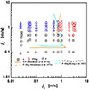 |
Fig. 3 Flow regime transitions for 203.2 mm horizontal pipe, comparative assessment with literature. P: plug, P-Slug: pseudo-slug, S: stratified [18]. |
Lin and Hanratty [6] conducted an experimental study on two-phase flow, focusing on the effect of pipe diameter on flow regime transitions in horizontal air–water systems. Their experiments utilized pipes with diameters of 25.4 mm and 95.3 mm under near-atmospheric conditions. The study primarily examined separated and intermittent flow regimes; their results revealed distinct transition mechanisms. Slug flow initiation shows strong diameter dependence at low gas velocities. The stratified to annular transition differed significantly: the 25.4 mm pipe transitioned via wave atomization deposition, while the 95.3 mm pipe used entrainment deposition. These results contradict with Taitel and Dukler [2] wave wetting theory. Small pipes transitioned via wave mixing at high liquid velocities (pseudo slug to annular), while large pipes used droplet entrainment. Pseudo-slugs diminished with diameter, vanishing completely when waves contacted the upper wall in large pipes, whereas small pipes’ thin films prevented this.
Abduvayt et al. [20] studied the effects of pressure and pipe diameter on gas–liquid two-phase flow behavior in 54.9 mm and 106.4 mm diameter pipelines; they found that pressure and pipe diameter significantly affect flow regime transitions lines. Higher pressure shifted boundaries to lower gas velocities, while larger diameters maintained stratified flow at increased liquid velocities. Liquid holdup decreased with gas velocity but varied with pressure and inclination. Both studies demonstrate how scale dependent mechanisms challenge universal flow transition models. Experimental characterization of horizontal gas–liquid two-phase flow revealed distinct sub flow regimes within stratified and intermittent flow patterns. These include smooth stratified, two-dimensional waves, three-dimensional waves, roll waves, entrainment droplet with roll waves, pseudo slug with roll waves, plug, less aerated slug, and highly aerated slug. Crucially, pipe diameter significantly influences the onset conditions for complex sub flow regimes, with larger diameters delaying transitions to flow regimes of higher complexity until higher gas velocities are attained. This foundational classification and diameter-dependent analysis were established through detailed experimental work [7]. The formation of liquid slugs is significantly controlled by both the pipe diameter and the design of the inlet mixer. Specifically, larger pipe diameters require higher liquid superficial velocities to trigger slug formation, as established through flow structure visualization studies.
Slug instability describes irregular variations in slug frequency, length, and velocity in horizontal gas–liquid flows, causing pressure and hydrodynamic fluctuations. Studies of Taitel and Dukler [2], Nydal et al. [21], Barnea et al. [22] show that a stable slug lengths typically range between 15 and 40 pipe diameters in horizontal and near-horizontal pipelines, this length is diameter-dependent rather than flow rate dependent. This relationship critically influences elongated bubble merging and interfacial structure, as slug length governs bubble movement. Research consistently identifies the velocity difference between a slug’s nose and tail as a governing mechanism for structural integrity [23]. Dukler and Hubbard [24] established the stability criteria for slug flow, requiring that the tail velocity of the elongated Taylor bubble be greater than or equal to the nose velocity and that the liquid film velocity behind the bubble equal the slug body velocity. According to Bendiksen et al. [25], slug flow reaches a stable condition when damping effects become dominant, causing the velocity at the front of the liquid slug (which coincides with the tail of the preceding elongated bubble) to equilibrate with the velocity at the slug tail. Deendarlianto et al. [5] experimentally validated these principles in 16 mm and 50 mm diameter pipes, they found that tail velocity consistently surpassed the nose velocity across all diameters, and that tail velocity decreased inversely with diameter. Larger diameters enhanced stability by reducing tail velocities, with 50 mm pipes forming elongated bubbles versus pseudo slugs in smaller diameters of 16 mm to 26 mm. This diameter-dependent behavior is due to wetted perimeter effects, where larger pipes reduce tail velocity of the elongated bubble below hydraulic jump thresholds. Consequently, stratified to slug transitions require higher liquid velocities in larger pipes, while pseudo slug to slug transitions need lower velocities.
Woods et al. [26] investigated frequency and development of slug in horizontal air–water two phase flow through 76.3 mm and 95 mm diameter pipes, examining effects of superficial gas and liquid velocities as well as pipe diameter on slug frequency. The study of fully developed slugs reveals an inverse relationship between diameter and slug frequency as shown in Figure 4 consistent with prior literature. Figure 4 compares slug frequency measurements for air–water flows in horizontal pipes of various diameters. The horizontal axis represents the liquid flow fraction also known as intermittency, I, defined as the fraction of time a slug is observed by a stationary observer, given by jf / (jf +jg), where jf is the superficial liquid velocity and jg is the superficial gas velocity (m/s). The vertical axis shows the dimensionless slug frequency fSD/jf, where fS is the slug frequency (s−1) and D is the pipe diameter. Interestingly, while slug frequency grows linearly with superficial liquid velocity, it hits a minimum when gas velocity reaches 4 m/s, matching the results reported by Fan et al. [27]. Woods emphasize the necessity of fully developed slugs. This is supported by the study of Greskovich and Shrier [28], who could not draw the conclusion because the slug flow failed to fully develop due to insufficient entrance when investigated pressure drop and holdup in horizontal slug flow using pipe diameters ranging from 38.1 mm to 154.1 mm. Tarahomi et al. [29] conducted research in two-phase flow by simulation in inner diameters of 52 mm and 38.1 mm with 10.4 m and 9.5 m in length respectively. They also scaled down diameters to 13 mm and 9.525 mm with length of 2.6 m and 2.5 m respectively. Results were compared and matched the experimental data from Ottens et al. [30] and Kong and Kim [19] across all flow regimes stratified, slug, bubbly, etc. The study show diameter significantly affects transition boundaries, larger pipes required higher superficial liquid velocity for bubbly to plug transition and higher superficial gas velocity for plug to slug transition as illustrated in Figure 5. Compared to smaller diameters, larger pipes consistently require higher superficial liquid velocity and higher superficial gas velocity values for flow regime changes.
The systematic investigations of da Silva et al. [31] further provides comprehensive evidence of the profound effect of pipe diameter on two-phase flow regime transitions, studying diameters from 27.3 mm to 102.7 mm, demonstrated that flow pattern transition boundaries are not universal, with larger diameters shifting the onset of intermittent slug flow and altering stratified flow structures. Complementing on this Fossa et al. [32] revealed that diameter also governs the internal physics of the resulting slug flow. Their work on 40 mm and 60 mm pipes showed that slug frequency scales inversely with diameter and, critically, that the fundamental mechanism triggering slug aeration changes with conduit size. This combined evidence firmly establishes pipe diameter as a critical parameter, controlling not only the transitions between flow regimes but also the intrinsic characteristics of the flows themselves.
Barnea et al. [22] studied two-phase flow in small horizontal pipes of diameter 4 mm to 12 mm, finding that capillary action causes liquid bridging and intermittent flow at low flow rates, unlike larger pipes which maintain stratified flow. They attributed this phenomenon to surface tension effects dominating in small pipes, as opposed to Kelvin–Helmholtz instabilities prevailing in larger diameter pipes. Their work reveals discrepancies with the Taitel and Dukler’s model for stratified to annular transitions in small pipes at low liquid rates. However, no explanation was provided for this discrepancy. Galbiati and Andreini [33] extended this research in stratified to annular transition in small horizontal tubes using diameters of 4 mm to 12.3 mm, incorporating surface tension effects into a modified version of the Taitel and Dukler’s model. The results reveal that gravity governs flow transitions in tubes with diameters greater than one millimeter, whereas surface tension dominates in capillary sized tubes with diameters of one millimeter or smaller, rendering the tube slope insignificant in such cases. They found that as diameter increases, gravitational forces outweigh surface tension effects. Incorporating surface tension significantly improved model predictions of the stratified to annular transition in small diameter tubes. The modified model demonstrates strong agreement with experimental data, effectively addressing the discrepancies found in earlier models. Brill et al. [34] studied two-phase flow in large diameter Prudhoe Bay pipelines using 304.8 mm and 406.4 mm diameters. They analyzed pressure losses, flow patterns, slug lengths, and holdup. They found that slug flow transitions occurred at lower liquid rates than predicted by Mandhane et al. [1] or Taitel and Dukler [2], indicating existing models needs scaling adjustments. Furthermore, slug lengths follow log normal distributions, enabling probabilistic maximum length estimates. This mechanistic model accurately predicts holdup in slug or bubbly flows, providing new insights into slug dynamics and overrun effects in large pipes.
Pipe diameter plays a critical role in governing interfacial wave dynamics in multiphase flows, directly influencing flow regime transitions and system stability. While surface tension dominates in small-diameter pipes, gravitational forces primarily control wave behavior in larger pipes. A thorough understanding of these scale-dependent mechanisms, framed through the lens of interfacial instability models, is essential for effective pipeline design and operational efficiency. This section reviews existing research on the influence of pipe diameter on wave characteristics, framed within the foundational perspective of linear stability theory and the subsequent nonlinear evolution of finite-amplitude waves.
The Kelvin–Helmholtz (K–H) instability is the primary linear stability model used to predict the initial onset of waves from a stratified interface. This analysis provides a critical velocity for instability but is limited to infinitesimal, initial wave growth. The work of Andritsos et al. [35] and Brauner and Maron [36] are key examples that explore the limits of this theory under the influence of diameter and fluid properties. Andritsos et al. showed that for viscous liquids greater than 20 cP, slugs form from small-wavelength K–H waves, contradicting classical inviscid theory but aligning with a viscous K–H model. Their finding that transition velocities were lower in a 25.2 mm pipe than in a 95.3 mm pipe highlights a direct diameter effect on the linear stability boundary. Building on this, Brauner and Maron [36] provided a crucial refinement for small diameters, demonstrating that the common assumption of infinite wavelength becomes invalid as the Eötvös number decreases below unity. In these small pipes, surface tension effects necessitate the consideration of finite-wavelength disturbances, causing the neutral stability curves (RC and ZRC lines) to diverge significantly from their behavior in large-diameter pipes where gravity dominates and infinite-wave models are valid. The foundational K–H analysis for horizontal flow was also extended by Taitel and Dukler [2], whose model for flow regime transitions is heavily based on a linear stability criterion and remains a benchmark, implicitly showing how the stability threshold varies with pipe diameter through the hydraulic depth.
Although Linear models predict the onset of waves, but nonlinear wave evolution models are required to describe their finite-amplitude growth, coalescence, and the subsequent transition to slug flow. The research of Deendarlianto et al. [5], provides critical insight into these diameter-dependent nonlinear processes. They examined air–water flow in 16 mm to 50 mm diameters, observing the evolution from stratified smooth flow to waves and finally to slugs. Their work highlights the role of wave coalescence, which is amplified by increasing the superficial gas velocity. Most importantly, they introduced a mechanistic framework based on the competition between the timescale for a wave to grow vertically to touch the pipe top and the timescale for it to grow axially. In larger diameters, the axial growth timescale dominates, which suppresses slug formation and favors the development of roll waves, thereby necessitating higher gas velocities for transitions. This sequential process of wave growth and slug formation is further illustrated by Lam et al. [37] and Akhlaghi et al. [38]. Their work shows how waves triggered by K–H instability grow, then later block the pipe, and form slugs, a process that varies with pipe diameter. Larger diameters favor roll waves due to the greater cross-sectional area that must be bridged and the different force balances at play. The study by Ruder et al. [39] also contributes to this understanding by detailing the formation of tiny bubbles behind wave tails, which is a key feature of the complex, nonlinear roll wave structure. Recent analyses by Barmak et al. [40], confirms that Froude-number scaling is only valid for D greater or equal to 100 mm, below which surface tension stabilization dominates. This underscores the critical need for scale-appropriate models that explicitly incorporate diameter-dependent transition criteria for reliable industrial application across all pipe sizes.
This review highlights the critical need for developing scale appropriate models that can properly account for diameter-dependent transition mechanisms across the full range of pipe sizes encountered in industrial applications. Table 1 summarizes experimental and theoretical studies on the effects of pipe diameter in horizontal two-phase flows, comparing flow regimes and geometric parameters across different investigations. All studies used air–water mixtures, except for those by Al-Wahaibi et al. [17] and Brill et al. [34], who used oil and water. Based on the observations in the table, slug flow has been widely studied in terms of diameter scaling, while bubbly flow is primarily analyzed in larger pipes. In contrast, studies on annular flow transitions remain limited. Small pipes tend to favor intermittent flow due to dominant inertial forces, although significant data gaps still exist for oil-water systems and diameters greater than 100 mm. Additionally, transitions from stratified to slug flow occur at lower liquid velocities in constrained geometries.
Experimental and theoretical studies on effect of pipe diameter on flow regime transitions in horizontal two-phase flow.
3 Effect of pipe diameter on interfacial waves
Pipe diameter plays a critical role in governing interfacial wave dynamics in multiphase flows, directly influencing flow regime transitions and system stability. While surface tension dominates in small-diameter pipes, gravitational forces primarily control wave behavior in larger pipes. A thorough understanding of these scale dependent mechanisms is essential for effective pipeline design and operational efficiency. This section reviews existing research on how pipe diameter affects wave characteristics, including wavelength, film thickness, and propagation velocity across various flow condition. While numerous studies [5, 35, 41] have investigated wave phenomena using Kelvin–Helmholtz instability theory, relatively few have explored the influence of pipe diameter on these wave characteristics. Andritsos et al. [42] experimentally studied the effect of liquid viscosity on the stratified to slug transition in horizontal pipes. They used pipe diameters ranging from 25.2 mm to 95.3 mm and liquid viscosities between 1 and 100 cP, finding that higher viscosities stabilize the flow, thus requiring greater liquid heights for slug formation. For viscous liquids greater than 20 cP, slugs arise from small wavelength Kelvin–Helmholtz waves, contradicting classical inviscid theory but matching viscous Kelvin–Helmholtz models. Furthermore, pipe diameter affects transitions lines differently based on viscosity: nonlinear processes dominate at low gas velocities, while large amplitude Kelvin–Helmholtz waves prevail at higher velocities. Additionally, the required superficial velocities in 25.2 mm diameter are lower than that of 95.3 mm diameter at same viscous liquids of one centipoise.
Brauner and Maron [43] studied the identification of the range of small diameters pipes, regarding two-phase flow regime transitions with Eötvös number less than one where surface tension dominates. Unlike Andritsos et al. [42] who assumed infinite waves, their analysis considered finite wavelength disturbances critical for small diameters. While large pipes show converging Real Characteristic (RC) and Zero Real Characteristics (ZRC) lines (validating infinite wave models), these diverge significantly in small pipes due to surface tension effects. The study established that the liquid height to diameter ratio (H/D) determines transition behavior, flows remain stratified wavy when the ratio (H/D) is less than 0.5, while H/D greater than 0.5 triggers flow regime transitions. For the intermediate range (H/D) approximately 0.5 produces large waves and pseudo slugs. This reveals how surface tension alters stability criteria in small conduits, challenging large pipe assumptions and providing a unified transition framework accounting for finite wavelength effects. Additionally, they find that in large pipe diameters, the RC and ZRC lines converge, making the assumption of infinite wave lengths valid. For pipes with an Eotvos number less than unity, surface tension effects dominate, defining the “small diameter” range. The Research by Cao et al. [13] systematically investigated diameter’s impact on slug frequency in horizontal pipelines using data from 26 mm to 300 mm pipes. Their analysis confirmed slug frequency is inversely proportional to diameter, as a larger cross-section reduces the liquid needed to form a slug and provides more space for slugs to coalesce. In annular flow, the experimental work of Schubring and Shedd [44], revealed a profound and non-uniform impact. Their study across 8.8 mm to 26.3 mm pipes showed wave frequency is so critically dependent on diameter that it required two distinct empirical correlations, indicating a fundamental shift in the underlying wave initiation mechanisms with scale. This evidence is complemented by Bae et al. [45], while studying a rectangular channel, benchmarked their observed wave-type progression against the classic work of Ottens et al. [46] in a 51 mm circular pipe, finding consistent fundamental phenomena. Collectively, these studies reveal a fundamental scaling challenge: while flow physics is consistent, predictive models for key parameters are highly diameter-specific. Consequently, laboratory-derived correlations cannot be directly applied to industrial-scale pipelines.
Lam et al. [37] and Akhlaghi et al. [38] well explained how gas–liquid density differences and velocity gradients trigger Kelvin–Helmholtz instability, forming waves that grow into slugs when critical film thickness and gas velocity are reached as illustrated in Figure 6. This sequential process of wave growth, amplification, pipe blockage, and slug propagation vary with pipe diameters, as larger diameters favor roll waves due to reduced surface tension and stronger gravity effects. Deendarlianto et al. [5] examined air–water flow in 16 mm to 50 mm diameters, observing stratified smooth flow at low superficial liquid velocity (jf) of 0.05 m/s, and superficial gas velocity (jg) of 0.7 m/s, evolving into viscous long wavelength waves, as noted by Lin and Hanratty et al. [6] and Soleimani and Hanratty [47]. Higher superficial liquid velocity raised liquid height until touching the upper wall, while higher superficial gas velocity increased turbulence, producing tiny bubbles behind wave tails forming roll waves, Ruder et al. [39]. Larger pipes require higher superficial velocities for transitions. Wave coalescence occurred via amplified superficial gas velocity, creating rough roll waves. At constant superficial gas velocity, increasing superficial liquid velocity forms pseudo slugs reaching the upper wall, though high superficial gas velocity disrupts them. They also observed that plug flow appeared only in 50 mm pipes, with larger diameters needing higher superficial liquid velocity for stratified to slug transitions but lower superficial liquid velocity for pseudo slug to slug shifts. The wave growth mechanism aligns with Kadri et al. [48] Kelvin–Helmholtz instability analysis, though it omits roll wave coalescence. Increased gas velocity near wave crests generates suction, counteracting gravity and lifting the interface. The model incorporates vertical wave growth and axial wave growth timescales Hanratty and Hershman [49]. Slug flow occurs when vertical wave growth is less than axial wave growth, while roll waves emerge if axial wave growth is less than vertical wave growth, as crests overtake downstream waves. The suppression of slugs in larger diameters is attributed to enhanced axial and vertical wave growth, a phenomenon that also delays the transition to roll waves by requiring higher gas velocities. As validated by the Maritime Simulation Tool (MAST) for pipe diameters from 25 mm to 95 mm, this diameter-dependent behavior is clearly depicted in Figure 7.
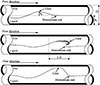 |
Fig. 7 Visualization of wave evolution (top), from growth (top) to roll waves (medium) or slug (bottom) [48]. |
Furthermore, the transitions between stratified, slug, and roll wave flow regimes across various pipe diameters and flow conditions were accurately predicted. Higher superficial liquid velocities accelerate the shift from stratified wavy to slug flow, while increased gas velocities promote roll wave formation through inertial forces rather than gravity dominated waves. A critical Froude number (Frcrit) of approximately 0.15 marks the boundary between gravity waves and roll wave flow regimes. Notably, larger pipe diameters demand greater gas velocities for the slug to roll wave transition, highlighting diameter-dependent hydrodynamic scaling.
In another study, Mandal et al. [50] studied oil-water flow in poly methyl methacrylate horizontal pipes of 12 mm and 25 mm diameters, the results reveal significant effect of pipe diameter. The narrower pipe shows greater interfacial waviness and transitioned to slug flow at higher velocities due to surface tension dominance, while the wider pipe maintains stratified or three-layer flows. Increasing oil flow in the small pipe produces elongated kerosene drops (resembling Taylor bubbles), eventually forming rivulet flows. In contrast, the larger pipe shows higher interfacial shear, increasing droplet dispersion and central layer thickness. This contradicts the work of Coleman and Garimella [51] who studied characterization of two-phase flow patterns in small diameter round and rectangular tubes and found that diameters greater than 10 mm had negligible effect. Unique flow regimes (rivulet, churn flows) emerged only in the 0.012 m pipe, attributed this to stronger surface tension and contact angle effects in confined spaces especially that kerosine was used in the experiment and shows that it wets the pipe wall more than water. However, broader validation across more diameters is needed for generalization. Sun et al. [52] experimentally quantified interfacial wave dynamics in horizontal air–water flow under heaving motion of amplitude between 2 mm and 12 mm, and frequency of 2–16 Hz, identifying six distinct flow regimes using differential pressure signals sampled at 500 Hz. Multi-scale entropy analysis revealed bubbly flow exhibited the highest entropy indicating maximal complexity, while annular flow shows the lowest Vibration parameters amplified interface fluctuations but did not alter flow regime transition boundaries, notably, frequency increased entropy values 15–20% more significantly than amplitude at small scales. For transitional flow regimes slug-wave, a two-dimensional multi-scale marginal spectrum entropy approach achieved 94.56% recognition accuracy across 100 flow conditions, resolving limitations of single-feature analysis. The study confirmed nonlinear oscillations enhance interfacial instability without changing fundamental transitions. Hudaya et al. [53] experimentally investigated interfacial wave characteristics in stratified air–water flow within a 26 mm inner diameter horizontal pipe. Superficial gas velocities ranges from 1.02 m/s to 3.77 m/s, and superficial liquid velocities ranged from 0.016 m/s to 0.092 m/s. Using flush-mounted constant electric current method (CECM) sensors and image processing, they identified distinct wave patterns: stratified smooth (flat interface), two-dimensional waves (periodic, small amplitude), roll waves (sudden liquid surges), and atomization (wavelet removal). Quantitative analysis revealed that the mean liquid hold-up decreased as superficial gas velocity increased, with an approximate reduction of 5–15% per 1 m/s increase in superficial gas velocity across tested superficial liquid velocity values. Wave velocity, determined via cross correlation of CECM signals, increased with rising superficial gas velocity. Conversely, in the two-dimensional wave region, the dominant wave frequency decreased with increasing superficial liquid velocity, as identified through power spectral density analysis.
The critical role of pipe diameter as a first-order parameter governing interfacial structures is consistently demonstrated across studies, though its specific effects manifest differently depending on the system and flow regime. Recent research by Cao et al. [13] has systematically investigated the impact of pipeline diameter on slug frequency in horizontal pipelines. Their comprehensive study utilized experimental data from two flow loops with diameters of 45 mm and 65 mm and incorporated data from other studies with pipe diameters ranging from 26 mm to 300 mm. The analysis robustly confirmed that slug frequency is inversely proportional to pipe diameter. This effect is attributed to the larger cross-sectional area, which reduces the liquid holdup required to form a bridging slug and provides a greater axial distance for slugs to coalesce and decay. The lower slug frequency in larger diameters results in longer, more developed slugs and larger gas pockets. This leads to a significantly different temporal and spatial void fraction profile compared to smaller pipes, characterized by longer periods of low void fraction (within the slug body) punctuated by longer periods of high void fraction (in the gas pocket). Consequently, the time-averaged void fraction is often higher in larger diameter pipes for the same flow conditions due to the increased volume occupied by the elongated gas pockets. The experimental work of Schubring and Shedd [44] provides a definitive quantification of this influence in horizontal annular flow, revealing a profound and non-uniform impact. Their study across 8.8 mm, 15.1 mm, and 26.3 mm pipes showed that wave frequency is so critically dependent on diameter that it necessitated two distinct empirical correlations, indicating a fundamental shift in the underlying wave initiation mechanisms with scale. This body of evidence is complemented by research that contextualizes findings within a broader diameter spectrum. For instance, Bae et al. [45], while primarily studying a rectangular channel, systematically benchmarked their observed wave-type progression against the classic work of Ottens et al. [46] in a 51 mm circular pipe, finding consistent phenomena. This chain of validation is extended by the fact that Ottens et al.’s flow regime data was itself used by Schubring and Shedd to help benchmark their own wave behavior models. Together, these studies create a coherent picture: while fundamental flow phenomena may be consistent across geometries and a range of diameters, as seen in the agreement between Bae et al., Ottens et al., and others, the specific, quantitative predictive correlations for key parameters like wave frequency are highly diameter-sensitive. This underscores a critical limitation: models developed for a specific pipe diameter cannot be universally extrapolated, highlighting an essential scaling challenge in applying laboratory-scale data to industrial-sized systems.
The dynamics of interfacial waves in gas–liquid two-phase flow are significantly impacted by pipe diameter, particularly in nuclear reactor coolant systems. In larger pipes, high-amplitude waves can lead to slug formation and cause time-varying thermal loads and flow-induced vibrations, contributing to thermal fatigue in critical piping components [54–56]. The lack of experimental data on wave behavior in pipes larger than 100 mm creates uncertainty in reactor safety analyses. Accurate predictions of wave coalescence and amplitude are essential for modeling interfacial heat and mass transfer during loss-of-coolant accidents, where cooling performance is closely tied to interfacial structure [57]. Advances in modeling, integrating viscous and inertial wave theories into computational fluid dynamics, are crucial for improving the predictive accuracy of reactor cooling systems [58].
In horizontal gas–liquid two-phase flows, pipe diameter (D) profoundly affects interfacial structures, such as the evolution of waves, liquid holdup, and transitions from stratified smooth to wavy or intermittent regimes. Traditional dimensionless groups like the Reynolds number (Re = ρ U D / μ), capturing inertial vs. viscous forces), Froude number (Fr = U /  ,) balancing inertial vs. gravitational forces), and Eötvös number (Eo = g Δρ D
2
/ σ), comparing buoyancy to surface tension) provide foundational scaling but often underperform for diameter variations, especially across lab-scale (D approximately 25mm to 100 mm) to industrial-scale (D greater than 300 mm) pipes. This is because these groups implicitly embed D, yet their standard forms assume geometric similarity without fully resolving diameter-induced changes in interfacial shear, wave coherence, and bubble or slug asymmetry. Larger D expands the stable stratified region to higher gas velocities. For small holdups (thin film), critical UG scales as
,) balancing inertial vs. gravitational forces), and Eötvös number (Eo = g Δρ D
2
/ σ), comparing buoyancy to surface tension) provide foundational scaling but often underperform for diameter variations, especially across lab-scale (D approximately 25mm to 100 mm) to industrial-scale (D greater than 300 mm) pipes. This is because these groups implicitly embed D, yet their standard forms assume geometric similarity without fully resolving diameter-induced changes in interfacial shear, wave coherence, and bubble or slug asymmetry. Larger D expands the stable stratified region to higher gas velocities. For small holdups (thin film), critical UG scales as  (gas Froude FrG is constant valid for D > 0.1 m). For small holdups, the scaling of the critical gas velocity by the gas Froude number is valid for pipe diameters larger than about 0.1 m [40].
For instance, Taitel and Dukler [2] identified five dimensionless groups, including a modified Froude number and a stratified equilibrium parameter, to govern flow-pattern transitions. Their model exhibits low sensitivity to pipe diameter (D) in small pipes (D < 50 mm), where high Eötvös number enhances surface tension dominance. However, as D increases, transition boundaries shift significantly due to enhanced gravitational stratification and reduced relative wall effects, expanding the stratified region to higher gas velocities. This highlights the need for D-explicit refinements, as unrefined groups fail to capture interfacial roughness or wave amplitude growth, leading to significant errors in pressure drop predictions in large-diameter systems. A key refinement involves hybrid dimensionless forms that incorporate D-scaling through additional terms like the pipe-to-wavelength ratio (λ/D) or confinement number (Co = 1/
 ), which quantifies surface tension confinement relative to buoyancy. Andritsos and Hanratty [35], used linear stability theory to predict stratified-wavy transitions in horizontal pipes (D equal to 25mm to 95 mm), defining WeG = ρG (USG)
2
D/σ for capillary-gravity waves via KH instability. Larger D shifts to irregular large-amplitude waves at moderate UG (0.5 m/s to 2 m/s) due to amplified inertial forces and coalescence.
), which quantifies surface tension confinement relative to buoyancy. Andritsos and Hanratty [35], used linear stability theory to predict stratified-wavy transitions in horizontal pipes (D equal to 25mm to 95 mm), defining WeG = ρG (USG)
2
D/σ for capillary-gravity waves via KH instability. Larger D shifts to irregular large-amplitude waves at moderate UG (0.5 m/s to 2 m/s) due to amplified inertial forces and coalescence.
Similarly, Hart et al. [59] developed empirical correlations for liquid holdup and frictional pressure drop in horizontal gas–liquid stratified flows with low liquid holdup (εL < 0.2), based on 1,500 air–water and air–oil data points in pipes of diameter range 26 mm to 154 mm. The correlations use (Eo= (gΔρ D 2 /σ), ReL and ReG with phase-specific hydraulic diameters (Dh, L= 4AL/PL, Dh, L =4AG/PG), and FrL to capture viscous and geometric effects on interfacial shear. These D-dependent terms refine the momentum balance, reducing average prediction errors in holdup and pressure drop to less than 10 % across the dataset. These refinements reveal that while core groups like Re, Fr, and Eo provide universality, explicit D-terms are essential for interfacial fidelity, preventing scale-up errors in regime maps and holdup predictions.
In summary, pipe diameter critically governs interfacial wave dynamics, flow regime transitions, and stability in multiphase flows. A focused analysis of diameter-dependent phenomena reveals distinct behavioral flow regimes, in small diameter pipes diameter less than 25 mm, and Eo less than one, surface tension dominates, promoting finite wavelength disturbances and requiring higher transition velocities for slug formation. Conversely, in large diameter pipes greater than 50 mm, with Eo much greater than one, the interfacial waves are governed by inertial forces, favoring roll wave development and exhibiting delayed slug formation at elevated gas velocities. Key findings demonstrate that the liquid layer thickness ratio (H/D) serves as an important transition criterion, while wave coalescence and interfacial curvature exhibit diametric trends between small and large pipe configurations. Notably, several critical knowledge gaps persist, particularly regarding intermediate pipe diameters. Table 2. Summarizes the literature on effect of pipe diameter on interfacial wave behavior in horizontal two-phase flow. The observations from Table 2. Indicates that most interfacial wave dynamics studies have focused on pipe diameters ranging from 10 mm to 100 mm. However, research on diameter exceeding 100 mm remains limited, particularly in the area of Computational Fluid Dynamics (CFD) simulations. Future research directions should prioritize experimental investigations of these underexplored configurations, coupled with advanced modeling approaches that integrate viscous Kelvin–Helmholtz theory for small diameters with inertial scaling methods for large pipes. Furthermore, focusing on CFD and extending existing CFD frameworks to high viscosity fluids would significantly enhance predictive capabilities for industrial applications. These insights collectively advance our fundamental understanding of diameter-dependent multiphase flow phenomena while identifying crucial areas for continued investigation to bridge existing knowledge gaps in the field.
Research overview of effect of pipe diameter on interfacial wave behavior in horizontal two-phase flow.
4 Effect of pipe diameter on void fraction distribution and phase distribution
The influence of pipe diameter on void fraction and phase distribution is crucial for the safety analysis of nuclear reactor cooling systems [62]. Larger pipes tend to promote gas coalescence and peaking, leading to heterogeneous void distributions that impact the accuracy of reactor safety codes. In large-break loss-of-coolant accidents, accurately predicting void fraction in large-diameter cold-legs and downcomers is essential for modeling emergency coolant delivery and system depressurization. Recent studies highlight the diameter dependence of drift velocity, a key parameter in system-level codes, introducing uncertainty in predictions. Density-wave instabilities, arising from feedback between wave propagation and pressure drop, further complicate these predictions [63]. The knowledge gap for intermediate diameters (25 mm to 50 mm), common in auxiliary and instrumentation lines, is particularly relevant. The lack of CFD-based research in this area limits predictive accuracy, and high-fidelity simulations are needed to complement system-level codes, enabling better phase distribution data for assessing localized cooling and thermal fatigue.in piping component [64]. The pipe diameter plays a critical role in governing void fraction and phase distribution characteristics in horizontal two-phase flows by fundamentally altering the dominant force balances (e.g., surface tension, inertial, and gravitational forces) and interfacial dynamics. While numerous studies have explored general void fraction behavior and phase distribution patterns [60, 65–69] the specific effects of diameter variation on these parameters remain relatively understudied, particularly across different flow regimes. Larger pipe diameters significantly modify key flow characteristics including flow regime transitions, bubble coalescence and breakup mechanisms, and overall system stability factors that have substantial implications for industrial applications ranging from petroleum pipelines to nuclear reactor systems. This section reviews existing literature to analyze the diameter-dependent effects on three critical parameters: void fraction distribution, drift velocity characteristics, and, phase distribution patterns, while identifying future directions in this important research area.
Gregory et al. [70] studied an in-situ volume fraction sensor for Two-Phase flows of non-electrolytes and found that pipe diameter weakly affects gas volume fraction in slugs though their correlation did not account for it. Subsequent studies by Gregory et al. [16] and Andreussi and Bendiksen [60], provided further insights, especially Andreussi and Bendiksen conducted experiments in 50 mm and 90 mm pipes using conductance probes. Their results demonstrate that the void fraction in liquid slugs depends significantly on pipe diameter, inclination, and fluid properties. They also introduced a minimum mixture velocity (UMf) that is required for appreciable void fractions in slugs, with this threshold varying with pipe diameter as shown in Figure 8. Furthermore, they found gas volumetric fraction in the slugs (ϵs) increases faster with mixture velocity in larger diameters, this observation contradict with Nydal et al. [21], who described the effect of diameter on void fraction in slug as very weak in their experiment using 53 mm and 90 mm diameter pipes.
In another study, Kong et al. [71] conducted an experimental study on the transition from plug to slug flow in horizontal pipes with inner diameters of 38.1 mm and 101.6 mm. Their objective was to quantify how factors such as superficial gas velocity, superficial liquid velocity, pipe size, and development length affect the evolution of void fraction, bubble size, and bubble velocity. The results shows that larger pipes exhibit a more uniform void fraction distribution due to the dominance of larger bubbles. While bubble size increases with pipe diameter, bubble velocity and variation intensity remain similar. Larger pipe sizes lead to larger bubble sizes, especially large slug bubbles. This increase is due to the more substantial space for bubble expansion in larger pipes. The flow area occupied by the gas layer was found to be comparable in both pipe sizes when normalized. However, the contribution from large bubbles to the total void fraction is significantly higher in the larger pipe. Larger pipe sizes tend to promote the formation of larger bubbles, especially for slug flow, and significantly alter the interfacial structure. This aligns with the findings of Kocamustafaogullari and Huang [72] who experimentally studied local and area-averaged void fractions, bubble sizes, and interfacial area concentrations in a horizontal air–water bubbly flow. Further examination on limited data in a 25.4 mm internal diameter pipe using the same bubble generation mechanism, lead to concluding that the mean bubble size appears to be significantly dependent on pipe diameter. Their results indicate that bubbles are smaller in the 25.4 mm pipe compared to a 50.3 mm pipe, though this observation could not be definitively confirmed due to insufficient data.
While interfacial area concentration and void fraction have been investigated by numerous researchers [3, 73–75] relatively few studies have systematically examined their relationship with pipe diameter. Addressing this knowledge gap, Kong et al. [76] recently conducted comprehensive experiments to evaluate a steady-state one-dimensional interfacial area transport equation for horizontal air–water bubbly flows across 38.1 mm, 50.8 mm, and 101.6 mm pipe diameters. Their experimental setup employed a four-sensor conductivity probe for precise measurements of bubble characteristics. The results demonstrate that bubble diameter differs in different pipe diameters, small pipes have bubbles with smaller diameter compared to larger pipes (Fig. 9). Kim et al. [77] demonstrates that pipe diameter critically influences two-phase flow by controlling flow regimes and bubble stability. In large pipes exceeding a critical size (Dc,max), slug flow is suppressed as bubbles break up due to surface instability. This necessitates diameter-specific models for bubble interactions in the Interfacial Area Transport Equation, as data from 9 mm to 304 mm pipes show that small and large diameters present unique challenges like intense intergroup transfer and distinct flow structures, preventing a one-size-fits-all modeling approach.
Abdul-Majeed and Al-Masha [78] studied slug liquid holdup in viscous two-phase flow, explicitly investigating the effect of pipe diameter through experiments in large-diameter (0.08 m and 0.1 m) pipes. Their data revealed that slug liquid holdup exhibits a slight but consistent increase with increasing pipe diameter, a trend they attributed to higher bubble rise velocities in larger pipes, which reduce gas residence time and thus increase the liquid fraction within the slug body. This finding directly contradicted the predictions of existing correlations, such as the model by Gomez et al. [79], which predicted a decrease in holdup with diameter. Furthermore Al-Safran et al. [80] correlations were found to predict an unrealistically strong and dominant effect of diameter.
In a related investigation, Kong et al. [81] experimentally characterized the local interfacial structure evolution during plug-to-slug transitions in horizontal air–water flows, comparing 38.1 mm and 101.6 mm pipe diameters. Their results demonstrate that larger diameters promote more uniform void fraction distributions, attributed to the prevalence of larger bubbles. While bubble size scales with pipe diameter, bubble velocity and fluctuation intensity exhibit minimal diameter dependence. The study identified two bubble types (small and large) in plug/slug flows, earlier these bubbles were classified by Ishii and Zuber [82] into two groups using chord length measurements.
Bubbles are classified as Group 1 (small) when chord length less than maximum bubble size (Dd,max) and Group 2 (large) when greater than Dd,max. These groups differ in interfacial area contribution to void fraction (α). While all pipes contain both types, small bubbles contribute more significantly to void fraction α. Kong et al. [81] reported that Group 2 bubbles constituted 88% of the void fraction (α) in large-diameter pipes versus 64% in smaller pipes. While bubble velocities showed no significant variation between groups, the Sauter mean diameter of Group 2 bubbles increased with pipe size. Group 1 bubbles were found to generate turbulence during their growth phase, which contributed to more uniform bubble distributions. Radial profiles of time-averaged void fraction revealed position-dependent bubble size variations. Notably, the transition from bubbly to plug or slug flow occurred at higher superficial liquid velocities in larger pipes, a phenomenon attributed to both more concentrated gas-phase distributions and enhanced bubble coalescence probability. Additionally, the critical void fraction for initiating transitions decreases with increasing pipe diameter.
In a similar study, Kong et al. [3] investigated pipe size effects (38.1 mm vs 101.6 mm) on horizontal two-phase flow, focusing on void fraction (α) and interfacial area concentration (αi) under bubbly flow conditions. The results show asymmetric gas phase distributions in both pipes, with higher void fraction and interfacial area concentration αi values near the top wall due to buoyancy. However, this peaking effect is more pronounced in the larger pipe, where α reached 0.132 in larger diameter pipe compared and 0.067 in the smaller diameter pipe under identical flow conditions (superficial liquid velocity and superficial gas velocity). The researchers attributed this to bubbles occupying a smaller portion of the flow area in large pipes, as buoyancy forces them against the top wall, this is illustrated in Figure 10. This compression effect leads to significantly greater peak void fraction values in larger diameter pipes.
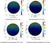 |
Fig. 10 Comparison of void fraction α and interfacial area concentration αi [1/m] at (jf = 6.00 m/s and USG = 0.15 m/s) in two pipes of different diameters [3]. |
Furthermore, Kong et al. [3] examined two key factors affecting interfacial structure in horizontal two-phase flow: Reynolds number (ReL) effects and geometric curvature. They found that decreasing curvature (from larger diameters) reduces circumferential turbulent fluctuations, promoting peaked gas distributions. Conversely, increasing ReL (which occurs with larger pipes at constant liquid superficial velocity jf) encourages more uniform gas distribution. These competing effects create an inverse relationship, with curvature effects proving dominant. Consequently, larger pipes exhibit more pronounced gas peaking than smaller pipes under identical conditions, aligning with findings by other researchers [83]. The results further show that increasing pipe size causes bubbles to concentrate near the top wall, reducing the flow area occupied by the bubble layer. Larger bubbles were observed in larger pipes due to increased coalescence. Although larger pipes show greater values bubble velocity fluctuation, fluctuation intensity remained comparable across pipe sizes. The increased bubble velocity fluctuation in larger pipes stems from higher liquid phase velocity fluctuations, this is similar to what Yang et al. [84] and Iskandrani and Kojasoy [85] observed. The near flow transition regions, neighboring bubbles influenced velocity fluctuations more significantly than liquid phase effects.
Andreussi et al. [86] investigated dispersed bubble flow in 18 mm and 50 mm diameter horizontal pipes, finding that maximum bubble size remains constant approximately 6 mm regardless of conditions or pipe diameter. Their Weber number (We) analysis shows higher We values in the 50 mm pipe due to reduced turbulent dissipation, while the 18 mm pipe’s greater turbulence enhanced bubble breakup. Buoyancy created a distinct void fraction peak near the upper wall. Talley et al. [87] expanded on this research, showing that higher gas flow rates increase the void fraction’s maximum value, while elevated liquid flow rates flatten its profile. They linked this observation to the surface tension forces small bubbles must overcome. Widyatama et al. [61] studied the interfacial behavior of air–water slug two-phase flow in horizontal pipes. The results show comparable trends in 16 mm and 50 mm diameter pipes but found that in narrower pipes, elongated bubbles shift toward the center and develop shorter tails. Bubble velocity rises with increasing gas and liquid superficial velocities. Notably, under identical flow conditions, bubbles in the 50 mm pipe travel faster than those in the 16 mm diameter pipe due to lower frictional losses, because friction is inversely proportional to pipe diameter. Conversely, the 16 mm diameter pipe exhibits higher slug frequency, this is attributed to its greater relative wall friction. These findings highlight how pipe diameter influences bubble dynamics, affecting void fraction distribution, velocity, and flow regime transitions.
In another study, Xu et al. [66] conducted an experiment using 25 mm and 50 mm diameter pipes, with the 50 mm pipe serving as the main tube and the 25 mm pipe as the bypass tube. The aim of the experiment was to investigate the holdup distribution of oil and water in horizontal two-phase flow. And utilizing the drift model to calculate the average oil hold up. The results show not only the influence of fluid flow rates on flow patterns and hold up but also the influence of pipe diameter on hold up, it is evident that at low water flow rates and low input oil fraction the holdup of main tube deviates from the bypass tube, although the gap is closed at higher oil fraction and eventually both pipes have evenly hold up distribution. Numerous studies have investigated slug front and tail velocities, with Nicholson et al. [88] developing correlation models. While earlier studies [24, 89] and recently Kong et al. [3] claimed pipe diameter negligibly affecting drift velocity, this contradicts the finding of Zukoski et al. [90] and Bendiksen et al. [25] who reported measurable effects. However Benjamin et al. [91] identified key parameters affecting drift velocity, including pipe diameter, gravity current, and phase distribution. Later França and Lahey [92] also find and emphasized diameter’s effect on translational velocity. Recently Bendiksen et al. [93] adopted the similar approach and investigated the potential effect of pipe diameter on slug velocity. They suggested that the bubble velocity (Ub) could be accurately predicted using a modified Nicklin correlation, aligning with the findings of Bendiksen et al. [25], Nicholson et al. [88]. The results show a sharp decrease in distribution parameter (Co) occurring at mean Froude number approximately one, where the value drops from 2.15 to within the range of 1.7–1.9, this was a narrow range change in mean Froude number. This transition corresponds to the bubble nose tip shifting upward radially as change in mean Froude number increases.
Wan et al. [94] studied diameter scaling effects on air–water slug flow in horizontal pipes from 27.86 mm to 108 mm, validating correlations against experimental data. Their analysis of the distribution parameter (C₀) and drift constant (C∞) demonstrated that pipe diameter significantly influences both parameters, a finding that challenges earlier model assumptions as shown in Figure 11, with smaller pipes producing longer slugs. The work highlights diameter’s crucial role in both flow parameters and slug length prediction. Smaller pipes produced longer slugs, confirming diameter’s role in slug dynamics, while the assumption that mean phase velocity (Vs) equals fluid mixture velocity (Um) held valid for most cases. In a recent study on gas–liquid two-phase flow in vibrating horizontal pipes with 15 mm to 25 mm diameter, Zhou et al. [9] found that void fraction does not change monotonically with pipe diameter. Their results show an initial increase in void fraction as diameter rose from 15 mm to 20 mm, followed by a decrease from 20 mm to 25 mm. They linked this trend to vibration-induced redistribution of phases and increased cross-sectional area enhancing buoyancy driven bubble rise.
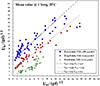 |
Fig. 11 Experimental evaluation of drift-flux parameters (C₀, C∞) for horizontal slug flow at 1 bar and 20 °C [94]. |
Building on earlier studies [95–97], Archibong-Eso et al. [98] advanced the investigation of slug flows by systematically evaluating the parameter of pipe diameter. Their experimental work in 25.4 mm and 76.4 mm pipes yielded a key finding: slug frequency decreases with larger pipe diameters due to increased space for slug coalescence and a lower tendency for the liquid level to block the pipe. Critically, they demonstrated that diameter is a primary variable controlling slug flow structure. A smaller pipe diameter increases slug frequency, which in turn leads to a lower time-averaged void fraction and more rapid fluctuations in its signal. This understanding of the diameter-frequency-void fraction relationship is vital for accurately predicting pressure gradients and designing pipelines for multiphase transport. Concurrently, Wijayanta et al. [99] observed that diameter influences flow regime transitions by altering the relative influence of gravitational and inertial forces, which can suppress intermittent flows in larger pipes.
This section demonstrates pipe diameter’s critical effect on void fraction distribution and phase distribution in horizontal two-phase flows. Larger diameters increase void fraction growth rates in slugs, some studies contradicts this for example the study of Nydal et al. [21] while pipes of diameter less than 25 mm enhance interfacial area concentration through confined bubble dynamics. Bubble behavior varies significantly, with large pipes favoring coalescence and gas peaking under identical conditions, whereas small pipes promote turbulence and uniform distributions. Flow transitions exhibit diameter dependence: small pipes produce frequent, long slugs, while large pipes delay slug formation but amplify roll waves. Drift velocity effects remain contested, with recent work by Wan et al. [94] challenging historical assumptions of diameter independence. Experimental studies are limited for intermediate diameters range of 25 mm–50 mm. These findings underscore the necessity of diameter specific models for accurate flow prediction. Future work should prioritize experimental validation across unexplored diameter ranges and advanced CFD development to address current limitations in industrial applications, from pipeline design to chemical processing systems. The collective evidence confirms pipe diameter as a fundamental parameter governing multiphase flow stability and flow regime transitions. Additionally, Table 3. summarizes key studies investigating the effects of pipe diameter on void fraction and phase distribution in horizontal two-phase flows. Notably, CFD based research remains underrepresented.
Key Studies on effects of pipe diameter on void fraction and phase distribution in horizontal two-phase flow.
5 Conclusion
This review has systematically examined the critical influence of pipe diameter on interfacial structures and flow regime transitions in horizontal gas–liquid two-phase flows. The synthesis of experimental, theoretical, and computational studies demonstrates that diameter fundamentally alters the balance of surface tension, gravitational, and inertial forces, resulting in scale-dependent behaviors. In small-diameter pipes typically less than 25 mm and Eötvös number less than one, surface tension dominates, stabilizing interfaces and promoting bubbly, slug, or intermittent flows while requiring higher liquid velocities for stratified-to-slug transitions. Conversely, in large-diameter pipes (usually greater than 100 mm) with Eötvös number much greater than one, gravity and inertia dominate, delaying annular and intermittent flows while favoring dispersed and stratified flows. Stratified flow persists to significantly higher gas velocities in larger pipes, and slug frequency decreases roughly inversely with diameter. Regarding interfacial structure and wave dynamics, small pipes exhibit finite-wavelength disturbances and suppressed waves, while large pipes promote roll wave formation due to diminished surface tension effects and enhanced inertial/gravitational forces. The ratio of liquid depth to pipe diameter emerges as a key criterion for flow transitions. Void fraction distributions become more asymmetric in larger pipes, with gas peaking near the top wall due to buoyancy concentrating bubbles in a smaller relative cross-sectional area. This effect, coupled with increased bubble coalescence, elevates the Sauter mean diameter in larger conduits.
However, existing predictive models, including flow regime transition frameworks (Taitel and Dukler) and void fraction correlations, frequently underperform in large-diameter systems (greater than 100 mm). These models, often developed for small or moderate diameters, fail to capture phenomena like blow-through and mischaracterize holdup profiles, slug stability, and transition boundaries. Dimensionless groups such as Reynolds, Froude, Eötvös numbers require refinement to accurately encapsulate diameter scaling effects across the full spectrum of pipe sizes.
Critical knowledge gaps persist, particularly for intermediate diameters from 25 mm to 50 mm, high-viscosity fluids, transient dynamics. Detailed interfacial wave characteristics and void fraction evolution in pipes exceeding 100 mm remain underexplored, and Computational Fluid Dynamics (CFD) studies incorporating validated diameter scaling are notably scarce as depicted in Tables 1–3. To address these limitations and advance industrial applications, such as nuclear reactor cooling systems and petroleum transport, future research must prioritize large-scale experiments (greater than 100 mm diameter) employing high-resolution diagnostics, development of advanced CFD scaling methodologies capable of handling larger and more complex geometries, with industrial validation, explicitly incorporating diameter-dependent force balances. Refined dimensionless frameworks and targeted studies on intermediate scales, high-viscosity fluids, and transient phenomena are equally essential.
This work demonstrates that pipe diameter is not merely a geometric parameter but a fundamental scaling variable dictating interfacial stability, phase distribution, and flow regime transitions. Advancing beyond universal correlations to develop diameter-adapted predictive models is essential for optimizing the design, safety, and efficiency of industrial two-phase flow systems. By pointing out the inconsistencies in scaling laws and advocating for diameter-informed design, this review lays a foundation for future research. It offers both a roadmap for navigating existing literature and clear guidance for advancing multiphase flow efficiency through the study of scaling effects. The work highlights the critical need for collaborative academia industry partnerships to bolster predictive modeling capabilities and address emerging challenges in large-scale two-phase flow systems.
Funding
This work is financially supported by the National Natural Science Foundation of China (12275059), and the Leading Scientific Research Project of China National Nuclear Corporation.
Conflicts of interest
The authors declare no conflicts of interest regarding this submission.
Data availability statement
Data availability statement is not applicable for this article.
References
- J.M. Mandhane, G.A. Gregory, K. Aziz, A flow pattern map for gas-liquid flow in horizontal pipes, Int. J. Multiph. Flow. 1(4), 537–553 (1974). https://doi.org/10.1016/0301-9322(74)90006-8. [Google Scholar]
- Y. Taitel, A.E. Dukler, A model for predicting flow regime transitions in horizontal and near horizontal gas-liquid flow, AIChE J. 22(1), 47–55 (1976). https://doi.org/10.1002/aic.690220105. [Google Scholar]
- R. Kong, S. Kim, S. Bajorek, K. Tien, C. Hoxie, Effects of pipe size on horizontal two-phase flow: Flow regimes, pressure drop, two-phase flow parameters, and drift-flux analysis, Exp. Therm. Fluid Sci. 96, 75–89 (2018). https://doi.org/10.1016/j.expthermflusci.2018.02.030. [Google Scholar]
- Y. Wang, Y. Yu, Z. Liu, Y. Chang, X. Zhao, Q. Wang, Experimental study on gas–liquid two-phase stratified flow at high pressure in a horizontal pipe, Energies 17(5), 1056 (2024). https://doi.org/10.3390/en17051056. [Google Scholar]
- A. Deendarlianto, A. Rahmandhika, A. Widyatama, O. Dinaryanto, A. Widyaparaga, Indarto, Experimental study on the hydrodynamic behavior of gas–liquid air–water two-phase flow near the transition to slug flow in horizontal pipes, Int. J. Heat Mass Transf. 130, 187–203 (2019). https://doi.org/10.1016/j.ijheatmasstransfer.2018.10.085. [Google Scholar]
- P.Y. Lin, T.J. Hanratty, Effect of pipe diameter on flow patterns for air–water flow in horizontal pipes, Int. J. Multiph. Flow. 13(4), 549–563 (1987). https://doi.org/10.1016/0301-9322(87)90021-8. [Google Scholar]
- A. Bouderbal, Y. Salhi, A. Arabi, E.-K. Si-Ahmed, J. Legrand, A. Arhaliass, Experimental investigation of different sub-regimes in horizontal stratified and intermittent gas–liquid two-phase flow: Flow map and analysis of pressure drop fluctuations, Chem. Eng. Res. Des. 210, 407–424 (2024). https://doi.org/10.1016/j.cherd.2024.08.029. [Google Scholar]
- M. Colombo, M. Fairweather, Prediction of bubbly flow and flow regime development in a horizontal air–water pipe flow with a morphology-adaptive multifluid CFD model, Int. J. Multiph. Flow. 184, 105112 (2025). https://doi.org/10.1016/j.ijmultiphaseflow.2024.105112. [Google Scholar]
- Y. Zhou, Y. Ran, Q. Liu, S. Zhang, Investigation on void fraction of gas–liquid two-phase flow in horizontal pipe under fluctuating vibration, Nucl. Eng. Des. 431, 113710 (2025). https://doi.org/10.1016/j.nucengdes.2024.113710. [Google Scholar]
- S.A. Ahmed, B. John, Liquid–Liquid horizontal pipe flow – A review, J. Pet. Sci. Eng. 168, 426–447 (2018). https://doi.org/10.1016/j.petrol.2018.04.012. [Google Scholar]
- N. Brauner, A. Ullmann, Modelling of flow pattern transitions in small diameter horizontal and inclined tubes, Exp. Therm. Fluid Sci. 148, 110965 (2023). https://doi.org/10.1016/j.expthermflusci.2023.110965. [Google Scholar]
- D. Bestion, The difficult challenge of a two-phase CFD modelling for all flow regimes, Nucl. Eng. Des. 279, 116–125 (2014). https://doi.org/10.1016/j.nucengdes.2014.04.006. [Google Scholar]
- Y. Cao, Q. Xu, H. Yu, B. Huang, T. Liu, L. Guo, Influence of pipeline diameters and fluid properties on slug frequency in horizontal pipelines, Chem. Eng. Sci. 283, 119397 (2024). https://doi.org/10.1016/j.ces.2023.119397. [Google Scholar]
- J. Weisman, D. Duncan, J. Gibson, T. Crawford, Effects of fluid properties and pipe diameter on two-phase flow patterns in horizontal lines, Int. J. Multiph. Flow. 5(6), 437–462 (1979). https://doi.org/10.1016/0301-9322(79)90031-4. [Google Scholar]
- W.P. Jepson, R.E. Taylor, Slug flow and its transitions in large-diameter horizontal pipes, Int. J. Multiph. Flow. 19(3), 411–420 (1993). https://doi.org/10.1016/0301-9322(93)90057-2. [Google Scholar]
- G.A. Gregory, M.K. Nicholson, K. Aziz, Correlation of the liquid volume fraction in the slug for horizontal gas–liquid slug flow, Int. J. Multiph. Flow. 4(1), 33–39 (1978). https://doi.org/10.1016/0301-9322(78)90023-X. [Google Scholar]
- T. Al-Wahaibi, Y. Al-Wahaibi, A. Al-Ajmi, R. Al-Hajri, N. Yusuf, A.S. Olawale, I.A. Mohammed, Experimental investigation on flow patterns and pressure gradient through two pipe diameters in horizontal oil–water flows, J. Pet. Sci. Eng. 122, 266–273 (2014). https://doi.org/10.1016/j.petrol.2014.07.019. [Google Scholar]
- Z. Li, G. Wang, M. Yousaf, X. Yang, M. Ishii, Flow structure and flow regime transitions of downward two-phase flow in large diameter pipes, Int. J. Heat Mass Transf. 118, 812–822 (2018). https://doi.org/10.1016/j.ijheatmasstransfer.2017.11.037. [Google Scholar]
- R. Kong, S. Kim, S. Bajorek, K. Tien, C. Hoxie, Experimental investigation of horizontal air–water bubbly-to-plug and bubbly-to-slug transition flows in a 3.81 cm ID pipe, Int. J. Multiph. Flow. 94, 137–155 (2017). https://doi.org/10.1016/j.ijmultiphaseflow.2017.04.020. [Google Scholar]
- P. Abduvayt, R. Manabe, N. Arihara, Effects of pressure and pipe diameter on gas–liquid two-phase flow behavior in pipelines, in: Paper presented at the SPE Annual Technical Conference and Exhibition, Denver, Colorado (2003), p. 15. https://doi.org/10.2118/84229-MS. [Google Scholar]
- O.J. Nydal, S. Pintus, P. Andreussi, Statistical characterization of slug flow in horizontal pipes, Int. J. Multiph. Flow. 18(3), 439–453 (1992). https://doi.org/10.1016/0301-9322(92)90027-E. [Google Scholar]
- D. Barnea, Y. Luninski, Y. Taitel, Flow pattern in horizontal and vertical two phase flow in small diameter pipes, Can. J. Chem. Eng. 61(5), 617–620 (1983). https://doi.org/10.1002/cjce.5450610501. [Google Scholar]
- J. Fabre, A. Liné, Modeling of two-phase slug flow, Ann. Rev. Fluid Mech. 24, 21–46 (1992). https://doi.org/10.1146/annurev.fl.24.010192.000321. [Google Scholar]
- A.E. Dukler, M.G. Hubbard, A model for gas–liquid slug flow in horizontal and near horizontal tubes, Ind. Eng. Chem. Fund. 14(4), 337–347 (1975). https://doi.org/10.1021/i160056a011. [Google Scholar]
- K.H. Bendiksen, An experimental investigation of the motion of long bubbles in inclined tubes, Int. J. Multiph. Flow. 10(4), 467–483 (1984). https://doi.org/10.1016/0301-9322(84)90057-0. [Google Scholar]
- B.D. Woods, Z. Fan, T.J. Hanratty, Frequency and development of slugs in a horizontal pipe at large liquid flows, Int. J. Multiph. Flow. 32(8), 902–925 (2006). https://doi.org/10.1016/j.ijmultiphaseflow.2006.02.020. [Google Scholar]
- Z. Fan, F. Lusseyran, T.J. Hanratty, Initiation of slugs in horizontal gas-liquid flows, AIChE J. 39(11), 1741–1753 (1993). https://doi.org/10.1002/aic.690391102. [Google Scholar]
- E.J. Greskovich, A.L. Shrier, Pressure drop and holdup in horizontal slug flow, AIChE J. 17(5), 1214–1219 (1971). https://doi.org/10.1002/aic.690170529. [Google Scholar]
- M.A. Tarahomi, M. Emamzadeh, M. Ameri, Scaling two-phase gas–liquid flow in horizontal pipes, Chem. Eng. Res. Des. 200, 592–601 (2023). https://doi.org/10.1016/j.cherd.2023.11.029. [Google Scholar]
- M. Ottens, H.C.J. Hoefsloot, P.J. Hamersma, Correlations predicting liquid hold-up and pressure gradient in steady-state (nearly) horizontal co-current gas–liquid pipe flow, Chem. Eng. Res. Des. 79(5), 581–592 (2001). https://doi.org/10.1205/02638760152424361. [Google Scholar]
- G. Gonçalves Da Silva, S. Vieira, M.S.D. Castro, F. Jaloretto Da Silva, Study of the pipe diameter effect on horizontal air–water two-phase flow, in: Procceedings of the 24th ABCM International Congress of Mechanicl Engineering (ABCM, 2017). https://doi.org/10.26678/abcm.cobem2017.cob17-1591. [Google Scholar]
- M. Fossa, G. Guglielmini, A. Marchitto, Intermittent flow parameters from void fraction analysis, Flow Meas. Instrum. 14(4–5), 161–168 (2003). https://doi.org/10.1016/S0955-5986(03)00021-9. [Google Scholar]
- L. Galbiati, P. Andreini, The transition between stratified and annular regimes for horizontal two-phase flow in small diameter tubes, Int. Commun. Heat Mass Transf. 19(2), 185–190 (1992). https://doi.org/10.1016/0735-1933(92)90030-L. [Google Scholar]
- J.P. Brill, Z. Schmidt, W.A. Coberly, J.D. Herring, D.W. Moore, Analysis of two-phase tests in large-diameter flow lines in Prudhoe Bay field, Soc. Pet. Eng. J. 21(3), 3 (1981). https://doi.org/10.2118/8305-PA. [Google Scholar]
- N. Andritsos, T.J. Hanratty, Interfacial instabilities for horizontal gas–liquid flows in pipelines, Int. J. Multiph. Flow. 13(5), 583–603 (1987). https://doi.org/10.1016/0301-9322(87)90037-1. [Google Scholar]
- N. Brauner, D.M. Maron, Analysis of stratified/nonstratified transitional boundaries in horizontal gas–liquid flows, Chem. Eng. Sci. 46(7), 1849–1859 (1991). https://doi.org/10.1016/0009-2509(91)87031-7. [Google Scholar]
- W. Lam Loh, V. Hernandez-Perez, N.D. Tam, T. Teik Wan, Z. Yuqiao, V.K. Premanadhan, Experimental study of the effect of pressure and gas density on the transition from stratified to slug flow in a horizontal pipe, Int. J. Multiph. Flow. 85, 196–208 (2016). https://doi.org/10.1016/j.ijmultiphaseflow.2016.06.005. [Google Scholar]
- M. Akhlaghi, V. Mohammadi, N.M. Nouri, M. Taherkhani, M. Karimi, Multi-Fluid VoF model assessment to simulate the horizontal air–water intermittent flow, Chem. Eng. Res. Des. 152, 48–59 (2019). https://doi.org/10.1016/j.cherd.2019.09.031. [Google Scholar]
- Z. Ruder, P.J. Hanratty, T.J. Hanratty, Necessary conditions for the existence of stable slugs, Int. J. Multiph. Flow. 15(2), 209–226 (1989). https://doi.org/10.1016/0301-9322(89)90071-2. [Google Scholar]
- I. Barmak, A. Gelfgat, N. Brauner, Instability of stratified air–water flows in circular pipes, Phys. Rev. Fluids. 9(9), 093901 (2024). https://doi.org/10.1103/PhysRevFluids.9.093901. [Google Scholar]
- P. Andreussi, L.N. Persen, Stratified gas–liquid flow in downwardly inclined pipes, Int. J. Multiph. Flow. 13(4), 565–575 (1987). https://doi.org/10.1016/0301-9322(87)90022-X. [Google Scholar]
- N. Andritsos, L. Williams, T.J. Hanratty, Effect of liquid viscosity on the stratified-slug transition in horizontal pipe flow, Int. J. Multiph. Flow 15(6), 877–892 (1989). https://doi.org/10.1016/0301-9322(89)90017-7. [Google Scholar]
- N. Brauner, D.M. Maron, Identification of the range of “small diameters” conduits, regarding two-phase flow pattern transitions, Int. Commun. Heat Mass Trans. 19(1), 29–39 (1992). https://doi.org/10.1016/0735-1933(92)90061-L. [Google Scholar]
- D. Schubring, T.A. Shedd, Wave behavior in horizontal annular air–water flow, Int. J. Multiph. Flow 34(7), 636–646 (2008). https://doi.org/10.1016/j.ijmultiphaseflow.2008.01.004. [Google Scholar]
- B. Bae, T. Ahn, J. Jeong, K. Kim, B. Yun, Characteristics of an interfacial wave in a horizontal air–water stratified flow, Int. J. Multiph. Flow. 97, 197–205 (2017). https://doi.org/10.1016/j.ijmultiphaseflow.2017.08.009. [Google Scholar]
- M. Ottens, K. Klinkspoor, H.C.J. Hoefsloot, P.J. Hamersma, Wave characteristics during cocurrent gas±liquid pipe flow, Exp. Therm. Fluid Sci. 9(3), 140–150 (1999). https://doi.org/10.1016/S0894-1777(99)00014-X. [Google Scholar]
- A. Soleimani, T.J. Hanratty, Critical liquid flows for the transition from the pseudo-slug and stratified patterns to slug flow, Int. J. Multiph. Flow. 29(1), 51–67 (2003). https://doi.org/10.1016/S0301-9322(02)00124-6. [Google Scholar]
- U. Kadri, R.F. Mudde, R.V.A. Oliemans, M. Bonizzi, P. Andreussi, Prediction of the transition from stratified to slug flow or roll-waves in gas–liquid horizontal pipes, Int. J. Multiph. Flow. 35(11), 1001–1010 (2009). https://doi.org/10.1016/j.ijmultiphaseflow.2009.07.002. [Google Scholar]
- T.J. Hanratty, A. Hershman, Initiation of roll waves, AIChE J. 7(3), 488–497 (1961). https://doi.org/10.1002/aic.690070330. [Google Scholar]
- T.K. Mandal, D.P. Chakrabarti, G. Das, Oil water flow through different diameter pipes, Chem. Eng. Res. Des. 85(8), 1123–1128 (2007). https://doi.org/10.1205/cherd06036. [Google Scholar]
- J.W. Coleman, S. Garimella, Characterization of two-phase flow patterns in small diameter round and rectangular tubes, Int. J. Heat Mass Transf. 42(15), 2869–2881 (1999). https://doi.org/10.1016/S0017-9310(98)00362-7. [Google Scholar]
- B. Sun, H. Chang, Y.-L. Zhou, Flow regime recognition and dynamic characteristics analysis of air–water flow in horizontal channel under nonlinear oscillation based on multi-scale entropy, Entropy 21(7), 667 (2019). https://doi.org/10.3390/e21070667. [Google Scholar]
- A.Z. Hudaya, H.Y. Kuntoro, O. Dinaryanto, Deendarlianto, Indarto, Experimental investigation on the interfacial characteristics of stratified air–water two-phase flow in a horizontal pipe, in: Presented at the Proceedings of the 3rd Aun/Seed-Net Regional Conference on Energy Engineering and the 7th International Conference on Thermofluids (Rcene/Thermofluid 2015) (Yogyakarta, Indonesia, 2016), p. 040012. https://doi.org/10.1063/1.4949300. [Google Scholar]
- T.R. Smith, J.P. Schlegel, T. Hibiki, M. Ishii, Two-phase flow structure in large diameter pipes, Int. J. Heat Fluid Flow. 33(1), 156–167 (2012). https://doi.org/10.1016/j.ijheatfluidflow.2011.10.008. [Google Scholar]
- U. Kadri, R.A.W.M. Henkes, R.F. Mudde, R.V.A. Oliemans, Effect of gas pulsation on long slugs in horizontal gas–liquid pipe flow, Int. J. Multiph. Flow. 37(9), 1120–1128 (2011). https://doi.org/10.1016/j.ijmultiphaseflow.2011.07.003. [Google Scholar]
- S.G. Haile, E. Woschke, G.S. Tibba, V. Pandey, Internal two-phase flow induced vibrations: A review, Cogent Eng. 9(1), 2083472 (2022). https://doi.org/10.1080/23311916.2022.2083472. [Google Scholar]
- H.-M. Prasser, M. Beyer, A. Böttger, H. Carl, D. Lucas, Influence of the pipe diameter on the structure of the gas–liquid interface in a vertical two-phase pipe flow, Nucl. Technol. 152(1), 3–22. https://doi.org/10.13182/NT05-A3657. [Google Scholar]
- Q. Lu, Y. Liu, J. Deng, X. Luo, Z. Deng, Z. Mi, Review of interdisciplinary heat transfer enhancement technology for nuclear reactor, Annal. Nucl. Energy. 159, 108302 (2021). https://doi.org/10.1016/j.anucene.2021.108302. [Google Scholar]
- J. Hart, P.J. Hamersma, J.M.H. Fortuin, Correlations predicting frictional pressure drop and liquid holdup during horizontal gas–liquid pipe flow with a small liquid holdup, Int. J. Multiph. Flow. 15(6), 947–964 (1989). https://doi.org/10.1016/0301-9322(89)90023-2. [Google Scholar]
- P. Andreussi, K. Bendiksen, An investigation of void fraction in liquid slugs for horizontal and inclined gas–liquid pipe flow, Int. J. Multiph. Flow. 15(6), 937–946 (1989). https://doi.org/10.1016/0301-9322(89)90022-0. [Google Scholar]
- A. Widyatama, O. Dinaryanto, Indarto, and Deendarlianto, The development of image processing technique to study the interfacial behavior of air–water slug two-phase flow in horizontal pipes, Flow Meas. Instrum. 59, 168–180 (2018). https://doi.org/10.1016/j.flowmeasinst.2017.12.015. [Google Scholar]
- D. Bestion, The physical closure laws in the CATHARE code, Nucl. Eng. Des. 124(3), 229–245. https://doi.org/10.1016/0029-5493(90)90294-8. [Google Scholar]
- L.C. Ruspini, C.P. Marcel, A. Clausse, Two-phase flow instabilities: A review, Int. J. Heat Mass Transf. 71, 521–548 (2014). https://doi.org/10.1016/j.ijheatmasstransfer.2013.12.047. [Google Scholar]
- T. Höhne, J.-P. Mehlhoop, Validation of closure models for interfacial drag and turbulence in numerical simulations of horizontal stratified gas–liquid flows, Int. J. Multiph. Flow. 62, 1–16 (2014). https://doi.org/10.1016/j.ijmultiphaseflow.2014.01.012. [Google Scholar]
- R. Kong, Q. Zhu, S. Kim, M. Ishii, S. Bajorek, K. Tien, C. Hoxie, Void fraction prediction and one-dimensional drift-flux analysis for horizontal two-phase flow in different pipe sizes, Exp. Therm. Fluid Sci. 99, 433–445 (2018). https://doi.org/10.1016/j.expthermflusci.2018.08.019. [Google Scholar]
- J. Xu, Y. Wu, Y. Chang, J. Guo, Experimental investigation on the holdup distribution of oil–water two-phase flow in horizontal parallel tubes, Chem. Eng. Technol. 31(10), 1536–1540 (2008). https://doi.org/10.1002/ceat.200800206. [Google Scholar]
- H. Barati, T. Hibiki, Integrating the two-group drift-flux and Sauter mean diameter models to predict the interfacial area concentration for gas–liquid flows in large-diameter pipes, Int. Commun. Heat Mass Transf. 164, 108747 (2025). https://doi.org/10.1016/j.icheatmasstransfer.2025.108747. [Google Scholar]
- L. Lei, J. An, F. Liang, C. Cheng, N. Zhou, Y. Ning, Z. Zhang, An experimental study on the void fraction for gas–liquid two-phase flows in a horizontal pipe, Fluid Dyn. Mater. Process. 17(5), 1037–1048 (2021). https://doi.org/10.32604/fdmp.2021.016081. [Google Scholar]
- L. Rossi, R. De Fayard, S. Kassab, Measurements using X-ray attenuation vertical distribution of the void fraction for different flow regimes in a horizontal pipe, Nucl. Eng. Des. 336, 129–140 (2018). https://doi.org/10.1016/j.nucengdes.2017.07.037. [Google Scholar]
- G.A. Gregory, L. Mattar, An in-situ volume fraction sensor for two-phase flows of non-electrolytes, J. Can. Pet. Technol. 12(2), (1973). https://doi.org/10.2118/73-02-06. [Google Scholar]
- R. Kong, A. Rau, C. Lu, J. Gamber, S. Kim, Experimental study of interfacial structure of horizontal air–water two-phase flow in a 101.6 mm ID pipe, Exp. Therm. Fluid Sci. 93, 57–72 (2018). https://doi.org/10.1016/j.expthermflusci.2017.12.016. [Google Scholar]
- G. Kocamustafaogullari, W.D. Huang, J. Razi, Measurement and modeling of average void fraction, bubble size and interfacial area, Nucl. Eng. Des., 148(2–3), 437–453 (1994). https://doi.org/10.1016/0029-5493(94)90124-4. [Google Scholar]
- S. Qiao, S. Kim, Interfacial area transport across a 90 vertical-upward elbow in air–water bubbly two-phase flow, Int. J. Multiph. Flow. 85, 110–122 (2016). https://doi.org/10.1016/j.ijmultiphaseflow.2016.05.015. [Google Scholar]
- D. Ryan, D. Kang, A. Dix, Z. Quan, S. Kim, Interfacial area transport modeling of air–water bubbly two-phase flows in inclined orientations, Nucl. Eng. Des. 428, 113530 (2024). https://doi.org/10.1016/j.nucengdes.2024.113530. [Google Scholar]
- H. Chen, S. Wei, W. Ding, H. Wei, L. Li, Interfacial area transport equation for bubble coalescence and breakup: developments and comparisons, Entropy 23(9), 1106 (2021). https://doi.org/10.3390/e23091106. [Google Scholar]
- R. Kong, S. Qiao, S. Kim, S. Bajorek, K. Tien, C. Hoxie, Interfacial area transport models for horizontal air–water bubbly flow in different pipe sizes, Int. J. Multiph. Flow. 106, 46–59 (2018). https://doi.org/10.1016/j.ijmultiphaseflow.2018.05.009. [Google Scholar]
- S. Kim, M. Ishii, R. Kong, G. Wang, Progress in two-phase flow modeling: Interfacial area transport, Nucl. Eng. Des. 373, 111019 (2021). https://doi.org/10.1016/j.nucengdes.2020.111019. [Google Scholar]
- G.H. Abdul-Majeed, A.M. Al-Mashat, A unified correlation for predicting slug liquid holdup in viscous two-phase flow for pipe inclination from horizontal to vertical, SN Appl. Sci. 1(1), 71 (2019). https://doi.org/10.1007/s42452-018-0081-0. [Google Scholar]
- L.E. Gomez, O. Shoham, Y. Taitel, Prediction of slug liquid holdup: horizontal to upward vertical flow, Int. J. Multiph. Flow. 26(3), 517–527 (2000). https://doi.org/10.1016/S0301-9322(99)00025-7. [Google Scholar]
- E. Al-Safran, C. Kora, C. Sarica, Prediction of slug liquid holdup in high viscosity liquid and gas two-phase flow in horizontal pipes, J. Pet. Sci. Eng. 133, 566–575 (2015). https://doi.org/10.1016/j.petrol.2015.06.032. [Google Scholar]
- R. Kong, A. Rau, S. Kim, S. Bajorek, K. Tien, C. Hoxie, Experimental study of horizontal air–water plug-to-slug transition flow in different pipe sizes, Int. J. Heat Mass Transf. 123, 1005–1020 (2018). https://doi.org/10.1016/j.ijheatmasstransfer.2018.03.027. [Google Scholar]
- M. Ishii, N. Zuber, Drag coefficient and relative velocity in bubbly, droplet or particulate flows, AIChE J. 25(5), 843–855 (1979). https://doi.org/10.1002/aic.690250513. [Google Scholar]
- M. Bottin, J.P. Berlandis, E. Hervieu, M. Lance, M. Marchand, O.C. Öztürk, G. Serre, Experimental investigation of a developing two-phase bubbly flow in horizontal pipe, Int. J. Multiph. Flow. 60, 161–179 (2014). https://doi.org/10.1016/j.ijmultiphaseflow.2013.12.010. [Google Scholar]
- J. Yang, M. Zhang, C. Zhang, Y. Su, X. Zhu, Quasi 3-D measurements of turbulence structure in horizontal air–water bubbly flow, Nucl. Eng. Des. 227(3), 301–312 (2004). https://doi.org/10.1016/j.nucengdes.2003.11.009. [Google Scholar]
- A. Iskandrani, G. Kojasoy, Local void fraction and velocity field description in horizontal bubbly flow, Nucl. Eng Des. 204(1–3), 117–128 (2001). https://doi.org/10.1016/S0029-5493(00)00361-7. [Google Scholar]
- P. Andreussi, A. Paglianti, F.S. Silva, Dispersed bubble flow in horizontal pipes, Chem. Eng. Sci. 54(8), 1101–1107 (1999). https://doi.org/10.1016/S0009-2509(98)00289-9. [Google Scholar]
- J.D. Talley, T. Worosz, S. Kim, Characterization of horizontal air–water two-phase flow in a round pipe part II: Measurement of local two-phase parameters in bubbly flow, Int. J. Multiph. Flow. 76, 223–236 (2015). https://doi.org/10.1016/j.ijmultiphaseflow.2015.06.012. [Google Scholar]
- M.K. Nicholson, K. Aziz, G.A. Gregory, Intermittent two phase flow in horizontal pipes: Predictive models, Can. J. Chem. Eng. 56(6), 653–663 (1978). https://doi.org/10.1002/cjce.5450560601. [Google Scholar]
- G.A. Gregory, D.S. Scott, Correlation of liquid slug velocity and frequency in horizontal cocurrent gas-liquid slug flow, AIChE J. 15(6), 933–935 (1969). https://doi.org/10.1002/aic.690150623. [Google Scholar]
- E.E. Zukoski, Influence of viscosity, surface tension, and inclination angle on motion of long bubbles in closed tubes, J. Fluid Mech. 25(4), 821–837 (1966). https://doi.org/10.1017/S0022112066000442. [Google Scholar]
- T.B. Benjamin, Gravity currents and related phenomena, J. Fluid Mech. 31(2), 209–248 (1968). https://doi.org/10.1017/S0022112068000133. [Google Scholar]
- F. França, R.T. Lahey, The use of drift-flux techniques for the analysis of horizontal two-phase flows, Int. J. Multiph. Flow. 18(6), 787–801 (1992). https://doi.org/10.1016/0301-9322(92)90059-P. [Google Scholar]
- K.H. Bendiksen, M. Langsholt, L. Liu, An experimental investigation of the motion of long bubbles in high viscosity slug flow in horizontal pipes, Int. J. Multiph. Flow. 104, 60–73 (2018). https://doi.org/10.1016/j.ijmultiphaseflow.2018.03.010. [Google Scholar]
- T.T. Wan, W.L. Loh, D.T. Nguyen, V.H. Perez, V.K. Premanadhan, Diameter scaling correlations for near atmospheric air–water slug velocities in horizontal pipe, J. Pet. Sci. Eng. 172, 349–359 (2019). https://doi.org/10.1016/j.petrol.2018.09.025. [Google Scholar]
- A. Archibong Eso, Y. Zhao, H. Yeung, ColloquiumComparison of electrical capacitance tomography and gamma densitometer measurement in viscous oil-gas flows, in: Presented at the the 2013 ukm fst postgraduate colloquium: in Proceedings of the Universiti Kebangsaan Malaysia, Faculty of Science and Technology 2013 Postgraduate, (Selangor, Malaysia, 2014), p. 81–89. https://doi.org/10.1063/1.4872090. [Google Scholar]
- Y.D. Baba, A.E. Archibong, A.M. Aliyu, A.I. Ameen, Slug frequency in high viscosity oil-gas two-phase flow: Experiment and prediction, Flow Meas. Instrum. 54,109–123 (2017). https://doi.org/10.1016/j.flowmeasinst.2017.01.002. [Google Scholar]
- B. Gokcal, A.S. Al-Sarkhi, C. Sarica, E.M. Al-Safran, Prediction of slug frequency for high-viscosity oils in horizontal pipes, SPE Proj. Facil. Constr. 5(3), 136–144 (2010). https://doi.org/10.2118/124057-PA. [Google Scholar]
- A. Archibong-Eso, Y. Baba, A. Aliyu, Y. Zhao, W. Yan, H. Yeung, On slug frequency in concurrent high viscosity liquid and gas flow, J. Pet. Sci. Eng. 163, 600–610 (2018). https://doi.org/10.1016/j.petrol.2017.12.071. [Google Scholar]
- S. Wijayanta, Deendarlianto Indarto, A. Prasetyo, A.Z. Hudaya, The effect of the liquid physical properties on the wave frequency and wave velocity of co-current gas–liquid stratified two-phase flow in a horizontal pipe, Int. J. Multiph. Flow. 158, 104300 (2023). https://doi.org/10.1016/j.ijmultiphaseflow.2022.104300. [Google Scholar]
Cite this article as: Sunga S, Daba MA, Abusah JL, Kocar C, Qiao S, et al. Effects of diameter on interfacial structure in horizontal two-phase flow: A review, Res. Des. Nucl. Eng. 2, 2025013 (2026), https://doi.org/10.1051/rdne/2025013.
All Tables
Experimental and theoretical studies on effect of pipe diameter on flow regime transitions in horizontal two-phase flow.
Research overview of effect of pipe diameter on interfacial wave behavior in horizontal two-phase flow.
Key Studies on effects of pipe diameter on void fraction and phase distribution in horizontal two-phase flow.
All Figures
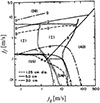 |
Fig. 1 Effect of pipe diameter on transition boundaries [2]. |
| In the text | |
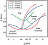 |
Fig. 2 Effect of superficial velocity on flow regime transition lines [5]. |
| In the text | |
|
Fig. 3 Flow regime transitions for 203.2 mm horizontal pipe, comparative assessment with literature. P: plug, P-Slug: pseudo-slug, S: stratified [18]. |
| In the text | |
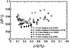 |
Fig. 4 Measurements of slug frequency for different pipe diameters [26]. |
| In the text | |
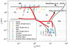 |
Fig. 5 Flow regimes classification results [29]. |
| In the text | |
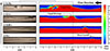 |
Fig. 6 Experimental and simulation results of slug formation over time [38]. |
| In the text | |
|
Fig. 7 Visualization of wave evolution (top), from growth (top) to roll waves (medium) or slug (bottom) [48]. |
| In the text | |
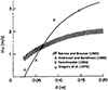 |
Fig. 8 Effect of pipe diameter on lower limiting velocity [60]. |
| In the text | |
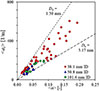 |
Fig. 9 Bubble size (Db) distribution across various pipe diameters [76]. |
| In the text | |
|
Fig. 10 Comparison of void fraction α and interfacial area concentration αi [1/m] at (jf = 6.00 m/s and USG = 0.15 m/s) in two pipes of different diameters [3]. |
| In the text | |
|
Fig. 11 Experimental evaluation of drift-flux parameters (C₀, C∞) for horizontal slug flow at 1 bar and 20 °C [94]. |
| In the text | |
Current usage metrics show cumulative count of Article Views (full-text article views including HTML views, PDF and ePub downloads, according to the available data) and Abstracts Views on Vision4Press platform.
Data correspond to usage on the plateform after 2015. The current usage metrics is available 48-96 hours after online publication and is updated daily on week days.
Initial download of the metrics may take a while.